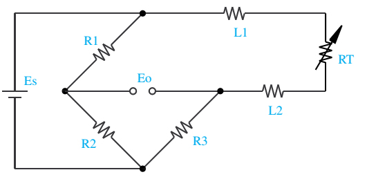
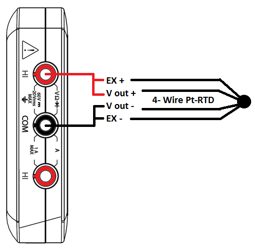
We'll be using 1 platinum series meter, pr11 probe + a d20 meter with an omega calibr. Es is the supply voltage;

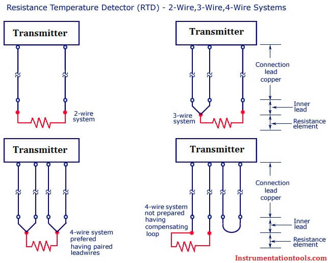
RTD (2wire, 3wire, 4wire)
In this uncompensatedcircuit, lead resistance l1 and l2.

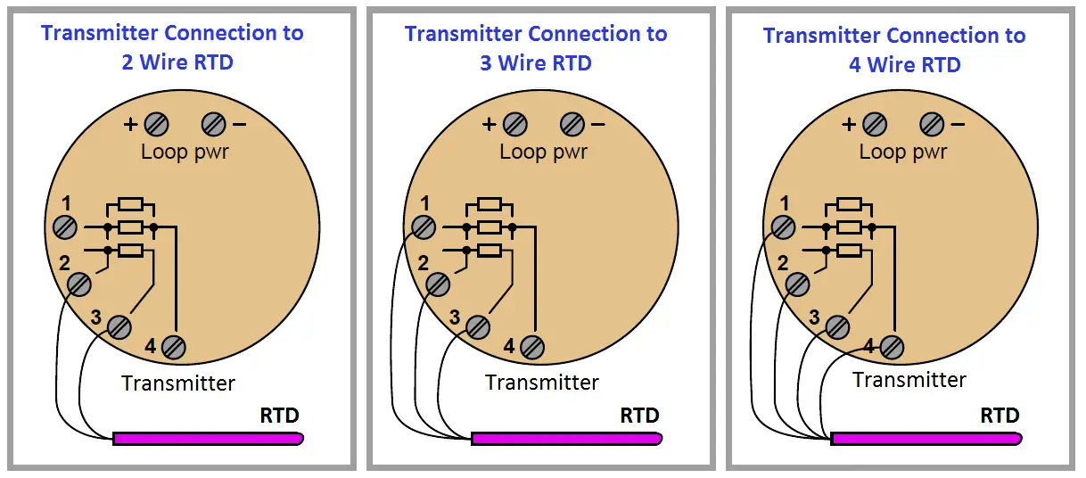
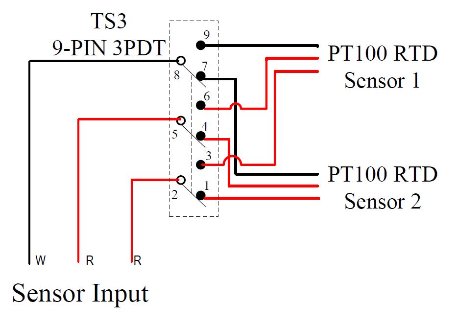
2 wire rtd wiring diagram. 3 wire pt100 rtd sensor wiring system. It is very important that each of the three wires used in the measuring circuit are equal in terms of both conductor size and length. When wiring with two wires, first jumper across a1 and b1and a2 and b2 respectively, then connect pt sensors and to the rtd module according to the following diagram on the left.
Voltage drop across the line resistance. And rt is the rtd. 2 wire rtd connections the 2 wire rtd configuration is the simplest among rtd circuit designs.
•idac generates the sensor excitation and the reference voltage. Signal conditioning circuit for pt100 temperature sensor scientific diagram rtd pinout features uses guide datasheet ohmic interfacing configuration 11 what is an working application principle of operation a resistance detector wiring tc inc difference between 2 wire. Pt100 temperature sensor wiring diagram.
2 wire rtd wiring diagram. R1 r2 and r3 are fixed resistors. Rtd wiring config adafruit max31865 pt100 or pt1000 amplifier learning system.
Eo is the output voltage; R1, r2, and r3 are fixed resistors; 2 wire rtd connections the 2 wire rtd configuration is the simplest among rtd circuit designs.
In this uncompensated circuit, lead resistance l1 and l2 add directly to rt. Rtd wiring configurations there are three types of wire configurations, 2 wire, 3 wire, and 4 wire, that are commonly used in rtd sensing circuits. 2 wire rtd wiring diagram.
In this uncompensatedcircuit, lead resistance l1 and l2. And rt is the rtd. Connection diagrams for rtd temperature probes and thermocouples to ensure uniform wiring of all temperature probes, jumo manufactures rtd temperature probes and thermocouples according to the jumo house standard.
The pt forestry is a rugged and. And rt is the rtd. Eo is the output voltage;
R1, r2, and r3 are fixed resistors; Eo is the output voltage; Es is the supply voltage;
Rtd pt100 3 wire wiring diagram gallery rtd sensors 2 3 4 wire rtd sensors resistance temperature detectors. •only one current source no mismatch. Rtd wiring configurations there are three types of wire configurations, 2 wire, 3 wire, and 4 wire, that are commonly used in rtd sensing circuits.
Pin on sensor interface circuits 2 wire rtd wiring diagram. Learn how to convert your 2 wire rtd into a 3 wire rtd. Here are tips how to wire your rtd to a meter by omega engineer, chet.
2 wire rtd wiring diagram. Using this method the two leads to the sensor are on adjoining arms. If the transmitter is mounted remotely from.
•noise and drift of the ref voltage are correlated and therefore canceled. In a basic 2 wire rtd the circuit adds the resistance of the lead wires to the resistance of the rtd. What is use of 2 wire rtd.
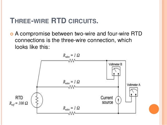
2 wire rtds are mostly used with short lead wires or where close accuracy is not required. The addition of a third wire, connected to one side of the measuring element, helps to compensate for the lead resistance. •up to 7 rtds are possible disadvantage:
Es is the supply voltage; As long as the junctions are near the rtd, as in a connection head, errors are negligible. Details of rtd wiring configurations for 2 wire, 3 wire and 4 wire rtd sensors.
R1, r2, and r3 are fixed resistors;

Dual Channel RTD Pt100 Temperature converter DAT2166
RTD Sensor Connections Inst Tools
2Wire RTD Support For NI 9216, NI 9217, NI 9226, and NI 9219 National Instruments

Resistance and RTD Input Mode (FAC2100) Product Documentation (Public) Fairmount Automation Wiki
2Wire RTD circuit CircuitLab

Rtd Pt100 3 Wire Wiring Diagram Free Wiring Diagram

RTD Head Mounted Temperature Transmitter DAT1010.

Resistance Temperature Detectors
Difference Between 2 wire RTD, 3 wire RTD, and 4 wire RTD's
Get 3 Wire Rtd Wiring Diagram Download
2 Wire Rtd Wiring Diagram

Temperature Sensors Temperature control solutions for home and industry
Chapter 7 Temperature Measurement RTD Measurement Circuits Engineering360
Measure Temperature using a RTD, myDAQ, and LabVIEW National Instruments
Rtds & thermistors
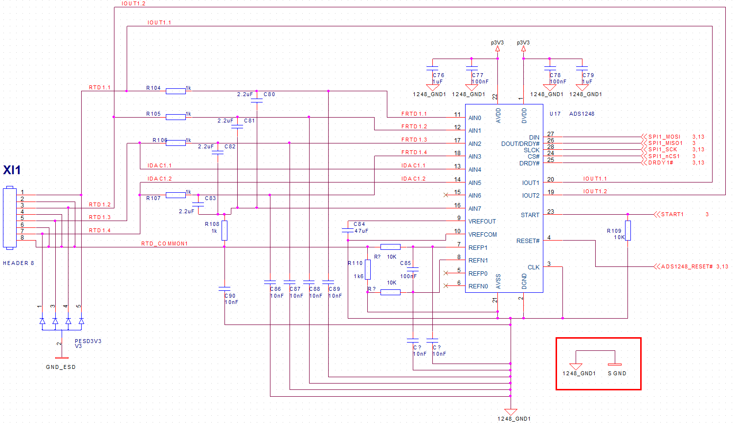
[Resolved] ADS1248 SCHEMATIC FOR 2WIRE PT1000 RTD Precision Data Converters Forum Precision
Oil and Gas Engineering 2 Wires, 3 Wires, or 4 Wires RTD (Resistance Temperature Detector)?

[MK_9839] Three Wire Rtd Wiring Diagram For Schematic Wiring
2 Wire RTD Wiring a 2 Wire RTD